I. Product Introduction
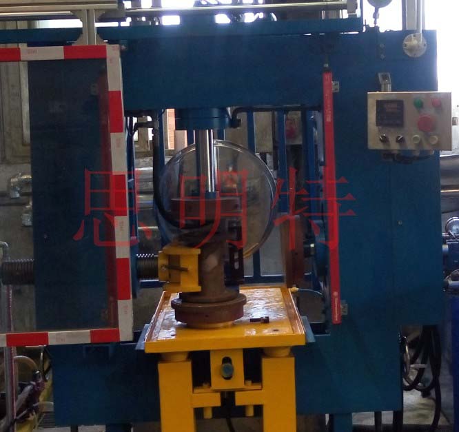
The three-way valve hydrostatic pressure testing machine professionally developed by Jinan Siminte Technology Co., Ltd. adopts a vertical structure. The whole machine is designed based on DN100 three-way pipe fittings, with a comprehensive testing range covering DN50~DN200 three-way pipes and straight pipes. The three-way valve hydrostatic pressure testing machine consists of a four-direction clamping mechanism, a hydraulic pressure system, hydraulic pipelines, water pipelines and protective devices. By conducting pressure tests on three-way valves, it can accurately measure performance indicators such as leakage rate, switching torque and operation flexibility of the valves under different pressures, so as to evaluate whether they meet relevant standards.
II. Structure Introduction of Three-way Valve Hydrostatic Pressure Testing Machine
1. Four-direction Clamping Mechanism
All clamping mechanisms adopt hydraulic drive, and the clamping force can be adjusted automatically or manually according to pipe fittings of different nominal diameters.
The vertical height of the clamping cylinders on both sides can be adjusted according to the size of different pipe fittings by means of a hand-operated lead screw.
The zero position of the clamping and sealing cylinder upon each return can be conveniently adjusted according to the size of pipe fittings. After each adjustment, the distance between the cylinder flange and the pressure-bearing pipe fitting flange shall be approximately 100 mm.
The thickness of the clamping flange shall be no less than40 mm, and the sealing rubber plate on the flange shall be easy to disassemble and fasten.
2. Water Pressure System
The high-pressure hydraulic force required for platen clamping is provided by the equipment’s own hydraulic boosting system. The test water pressure system consists of a large-flow low-pressure water pump, a small-flow high-pressure water pump, as well as pipelines and control valves.
When testing pipe fittings, the large-flow low-pressure water pump is activated to fill the pipe chamber with test medium. After the low-pressure water is fully filled, the system automatically starts the high-pressure water pump to deliver high-pressure water into the pipe fitting. When the test medium pressure reaches the preset value, the high-pressure water pump stops automatically, and the system switches to the pressure holding timing mode (holding time can be set by the operator). When the pressure holding time expires, the corresponding indicator lights up and the buzzer alarms simultaneously.
The structure adopts bottom water inlet and top air venting: the water inlet pipe is installed on the bottom sealing baffle, and the air vent is set on the upper platen, ensuring complete air evacuation from the pipe chamber during water pressure testing.
An air evacuation detection device shall be installed on the exhaust pipeline. Upon detection of full air evacuation, the low-pressure water supply stops automatically, and high-pressure water filling starts automatically. During the entire pressure holding period, high-pressure water is continuously supplied until the holding time ends, after which the high-pressure water supply stops and the system automatically releases pressure.
Two sets of safety valves shall be installed on the high-pressure water circuit to automatically discharge excess pressure when the water pressure exceeds the set high limit.
3. Hydraulic and water pipe system
Hydraulic oil pipe
All hydraulic oil pipes shall be pickled. The hydraulic manifold blocks shall be made of ductile iron, and treated with pickling and nickel plating.
All water pipelines shall be made of stainless steel. The high-pressure water pump must have a stainless steel inner wall. The inner wall of the water storage tank shall also be made of stainless steel grade 316 or higher.
The hydraulic system shall be equipped with an automatic pressure relief device. When the equipment is in standby mode, the entire hydraulic system relieves pressure automatically. When any hydraulic action is to be performed, the system pressure automatically restores to the normal value, so as to reduce oil temperature and energy consumption, and prolong the service life of the oil pump, motor and hydraulic components.
4.Guards
The pressure testing machine is equipped with the following protective devices (not limited to these):
All rotating parts shall be covered with sturdy protective covers. The covers shall be made of 4 mm thick steel plate, and all heavy protective covers shall be equipped with inspection windows.
Pipe fittings under pressurization and pressure holding shall be enclosed in a fully enclosed but transparent space to prevent injury caused by splashing from high-pressure components.
The transparent protective cover shall be interlocked with the hydraulic / water pressure system. If the safety protective cover (door) is not securely closed, the high-pressure water system shall not operate. When the safety door is open, the control sections of all moving mechanisms are locked, and moving parts cannot move.
There shall be at least two transparent protective doors, front and rear. The front door shall be driven by a pneumatic or hydraulic cylinder, and the rear door may be manually operated. A signal indication shall be provided when the protective doors are properly closed.
The transparent material of the protective doors shall be tempered glass with a thickness of at least 6 mm.
The front protective door shall be provided with two separately operated buttons and status indicators.
The control system shall support both manual and automatic operation modes. Automatic mode is used for normal production, while manual mode is used for commissioning and maintenance.
In automatic mode:
Press the start button, and the protective door closes automatically. After confirming that the protective door is fully closed via limit switches, each mechanism automatically starts clamping the pipe fitting. After clamping, the system automatically performs low-pressure water filling and air evacuation, followed by automatic high-pressure water injection and automatic pressure holding timing. Upon completion of timing, the system alerts the operator with audible and visual signals. The operator then presses the pressure relief button; the system automatically relieves pressure, and all clamping mechanisms automatically retract to their initial positions. The upper clamping beam may then be swung open manually (via button, depending on workpiece weight). The safety door opens automatically under button control. The pipe fitting is then lifted out by a hoist or removed manually.
In manual mode:
Each mechanism can be operated individually in inching (jog) mode.
III. Technical Requirements for Three-way and Four-way Valve Hydrostatic Pressure Testing Machines
|
Technical requirement |
Technical data |
1 |
name |
Three-way Valve Hydrostatic Pressure Testing Machine-Four-way Valve Hydrostatic Pressure Testing Equipment |
2 |
Quantity |
1 |
3 |
Type |
Vertical type |
4 |
Usage |
Carry out hydrostatic tightness tests on pipe fittings ranging from DN50 to DN200. |
5 |
Location |
Pipe Fitting Hydrostatic Test Workshop |
7 |
Fitting data |
Straight pipes, tees and cross tees, with a nominal diameter range of DN50 to DN200. |
8 |
Nominal Pressure Range |
PN16/PN25 水压压力6.0Mpa |
9 |
Permissible Structural Length of Test Pipe Fittings |
200-550 mm |
10 |
Permissible Outer Diameter of Flange / Socket for Test Pipe Fittings |
Φ60-Φ460 mm |
12 |
Opening Distance Between Left and Right Pressure Plates |
250-600 mm |
13 |
High-pressure Water Pump |
316 stainless steel inner wall |
14 |
Low-pressure Water Pump |
Flow rate ≥ 10 m³/h |
15 |
Pressure Gauge |
Equipped with both shock-resistant analog pressure gauges and digital display gauges |
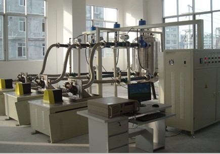
The oil cooler oil-water performance testing machine is used to measure relevant parameters of the oil cooler, including heat dissipation (power), oil outlet temperature, water outlet temperature, oil inlet and outlet pressures, oil pressure difference, coolant inlet and outlet pressures, coolant pressure difference, and heat transfer efficiency, under test conditions specified in the technical specifications such as oil inlet temperature, water inlet temperature, oil flow rate, and coolant flow rate.
It is capable of controlling and measuring water-side and oil-side parameters related to the test, as well as the flow rate, power and efficiency of the water pump.
Oil Cooler Oil-Water Performance Testing Machine
femenshiyanji-f
|